EN
 fr
 de
 es
 it
 ru
 pt
 ar
 id
 ms
 uk




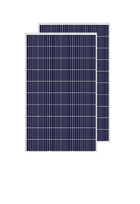


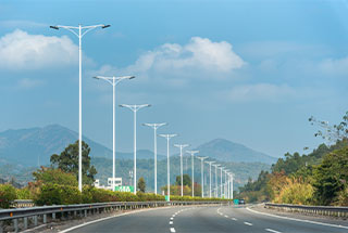
We have cooperated with more than 200 countries in solar energy projects and road lighting projects. We have exported products to many countries and participated in many important government projects around the world.




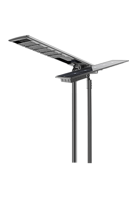


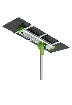
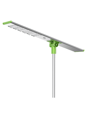
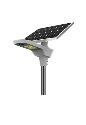


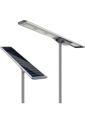
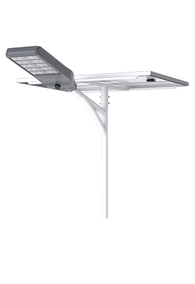
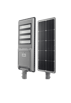
We have cooperated with more than 200 countries in solar energy projects and road lighting projects. We have exported products to many countries and participated in many important government projects around the world.

Anern has 17 years of experience in solar lighting and solar product manufacturing. Anern is headquartered in Guangzhou. With a production base of 30,000 square meters, our company has an R&D team of more than 100 people.
Solar street light spacing should be established through a lighting calculation for the actual road, luminaire, mounting arrangement, and operating schedule. Wattage or a fixed pole-height multiplier cannot confirm that the spaces between poles receive enough light. Dark gaps often appear when a layout is selected from a product photo or a claimed illumination area without checking minimum light levels.
For road projects, the objective is useful visibility across the required area throughout the night. That means considering coverage, uniformity, glare, and the reduced output that may occur under programmed dimming. Solar charging and battery capacity must then support the lighting performance on which the spacing depends.
Electrical watts measure power input, not the amount of light reaching a point on the road. Luminous flux, expressed in lumens, describes emitted light, while the optical distribution determines where that light travels. Two luminaires with the same electrical power can produce different road coverage and different minimum levels between poles.
Even matching lumen values do not guarantee matching layouts. A broad distribution may send more light outside the useful road area, while a narrower distribution may create a bright patch below the pole and leave a weak midpoint. Glare and spill light also matter, so increasing power is not always an effective correction.
When reviewing a solar LED street light, request the photometric file for the exact optical and output configuration. Confirm whether the listed wattage describes measured luminaire input, a product series designation, or a claimed equivalent. The layout should use verified light output and distribution at the operating setting that will actually be supplied.
Road width determines how far the luminaire must project across the carriageway. Mounting height, pole setback, arm outreach, tilt, and luminaire orientation influence both the near and far edges. A layout that works for a narrow access road may leave the opposite lane or sidewalk underlit on a wider road.
Increasing mounting height can spread light over a larger area, but it also changes the illuminance on the road and may require different optics or output. The result must be recalculated rather than estimated from height alone. Trees, overhead obstructions, bends, gradients, and parked vehicles can also affect the useful illuminated area.
Measure the road and pedestrian zones separately. A carriageway calculation does not automatically confirm visibility on a sidewalk, at an entrance, or across a pedestrian crossing. Identify the lighting criteria accepted by the responsible authority before fixing pole positions. Pole foundations, structural loading, and roadside clearance require their own engineering checks.
Choose the beam to suit the geometry. A roadway optic may distribute light farther along the road while limiting wasted light behind the pole. A more symmetric distribution may be useful for an open area, but it should not be assumed suitable for a narrow road simply because it covers a large advertised area.
The photometric file records intensity in different directions and allows the designer to calculate the combined contribution from neighboring luminaires. Check that the file matches the LED package, lens, drive setting, and mounting orientation. A file for another wattage or optic can produce an attractive simulation that does not represent the delivered equipment.
Adjustable LED modules add another variable. If a modular solar street light uses adjustable modules, document their installed angles and use corresponding photometric information. Increasing tilt to reach a distant point can also increase glare and light beyond the intended boundary. Adjustment should follow a verified design, not only a visual impression from directly under the pole.
A one-sided layout places all poles along one edge. It can reduce the number of mounting locations, but coverage at the far edge needs careful checking. Staggered layouts alternate sides and may help distribute light across a wider area. Opposite layouts use poles on both sides at corresponding positions and create a different overlap pattern.
None of these arrangements guarantees compliance by itself. Compare them with the same road geometry, luminaire data, maintained output assumptions, and acceptance criteria. Also define spacing precisely: distance between poles on the same side is not the same as the longitudinal interval between alternating poles in a staggered arrangement.
Layout | Question the lighting calculation must answer |
One-sided | Are the opposite edge and the midpoint between poles adequately lit? |
Staggered | Does alternating coverage maintain the required minimum across the road? |
Opposite | Does additional overlap improve coverage without excessive glare or bright patches? |
Median-mounted | Are both carriageways covered while structural and roadside constraints are satisfied? |
Intersections, curves, crossings, and road endings may require local adjustments rather than a repeated standard interval. Treat these areas as part of the design from the beginning; adding them after a uniform pole count has been ordered can change the equipment quantity and layout.
Use a recognized lighting calculation method with an appropriate grid covering the required area. Evaluate the applicable metrics, which may include road luminance, horizontal or vertical illuminance, uniformity, and glare. The chosen criteria depend on the road classification, users, and local requirements; there is no single lux target for every street.
Uniformity conventions must be stated explicitly. For an illuminance example, minimum-to-average uniformity is Emin divided by Eavg, while average-to-minimum is the reciprocal. A hypothetical layout with Eavg of 10 lx and Emin of 2 lx has Emin/Eavg of 0.20 and Eavg/Emin of 5.0. Both ratios describe the same illustrative distribution; the applicable project criteria determine whether it is acceptable.
Inspect the contour map and minimum points as well as the summary average. A satisfactory average can hide a dark area between poles or along a curb. Apply appropriate maintenance assumptions for dirt and lumen depreciation rather than using initial output as though it will remain unchanged indefinitely.
For an all-in-one solar street light, also confirm that the solar-panel orientation needed for charging is compatible with the required luminaire orientation. Integrated geometry can constrain those choices. After installation, verify pole positions, aiming, operating modes, and representative light levels against the design conditions.
It can reduce light in already weak areas below the required minimum. If every luminaire dims by the same proportion and the distribution remains unchanged, the mathematical uniformity ratio can remain approximately constant while absolute illuminance falls. A layout can therefore retain its uniformity ratio and still provide insufficient light.
Unequal dimming creates another problem. Different schedules, sensor triggers, battery conditions, or controller settings can produce uneven output along the road. Turning off alternate luminaires changes the overlap pattern and can create larger gaps; it should not be treated as equivalent to dimming all luminaires together.
Model every intended operating stage, including the lowest programmed output. For motion control, consider the area illuminated before a person or vehicle reaches the detection zone, the response time, and the return to the lower setting. A bright demonstration immediately after a sensor trigger does not represent the background lighting for the rest of the night.
The energy system must sustain the approved schedule under the site's design conditions. Insufficient charging can cause unplanned output reduction or early shutdown. Review the solar resource, shading, usable battery energy, and required autonomy alongside the lighting calculation rather than assuming a full battery every evening.
There is no universal distance suitable for every road and product. Determine spacing from the applicable lighting criteria, geometry, photometric data, and operating schedule. Rules of thumb can provide starting points, but they do not verify the finished design.
Not necessarily. The cause may be unsuitable optics, incorrect aiming, excessive spacing, or an obstruction. More output can also increase glare and battery demand, so recalculate the layout before changing wattage.
No. Minimum levels, the specified uniformity metric, glare, and other required visibility measures must also be assessed. Look at the locations of weak points rather than relying only on a summary average.
No. Test the intended reduced-output modes and verify the controller schedule. If the design depends on sensor activation, assess background output and detection behavior as well as the triggered state.
Reliable solar street light spacing comes from matching optics and mounting geometry to the road, then checking the resulting minimum levels and uniformity. Verify the exact product data, every planned dimming stage, and the energy needed to sustain them. This approach exposes dark gaps before pole positions and equipment quantities are finalized.
· Federal Highway Administration — 2023 FHWA Lighting Handbook. Lighting calculations, geometry, uniformity, and photometric design.
· Federal Highway Administration — Guidelines for the Implementation of Reduced Lighting on Roadways. Research guidance on dimming and adaptive roadway lighting.
· U.S. Department of Energy — Purchasing Energy-Efficient Exterior Lighting. Exterior luminaire efficiency, performance data, and controls.