EN
 fr
 de
 es
 it
 ru
 pt
 ar
 id
 ms
 uk


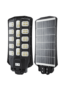
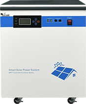


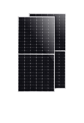
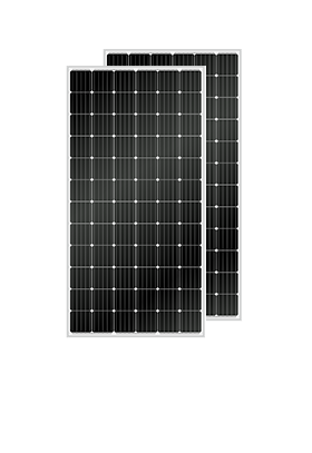
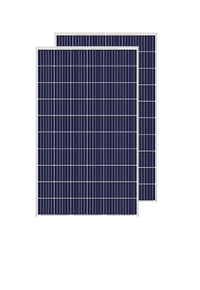



We have cooperated with more than 200 countries in solar energy projects and road lighting projects. We have exported products to many countries and participated in many important government projects around the world.




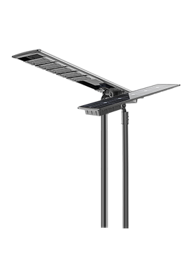


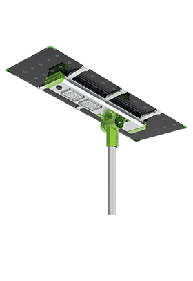
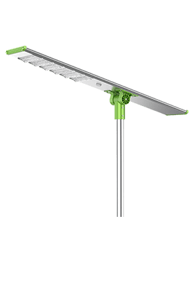
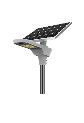


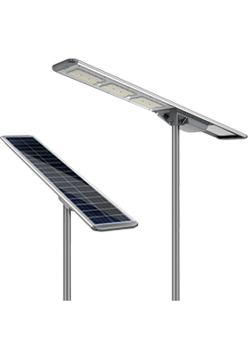
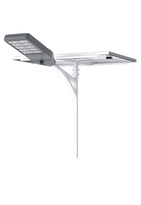
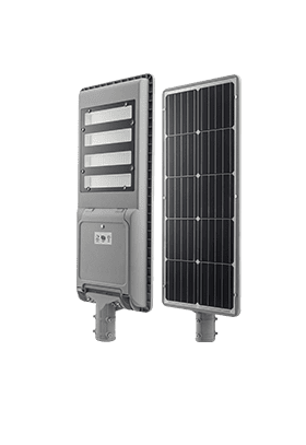
We have cooperated with more than 200 countries in solar energy projects and road lighting projects. We have exported products to many countries and participated in many important government projects around the world.

Anern has 17 years of experience in solar lighting and solar product manufacturing. Anern is headquartered in Guangzhou. With a production base of 30,000 square meters, our company has an R&D team of more than 100 people.
Converting DC to AC is the core function of every modern solar, backup power, and off-grid system, and it is achieved using an electronic device called an inverter that switches DC rapidly to synthesize an AC waveform. This guide explains the fundamentals, circuit mechanisms, and practical technologies from an engineering and project-design perspective.
DC to AC power conversion is the process of electronically switching a DC source to create an alternating voltage/current at a target frequency (typically 50/60 Hz) and RMS voltage.
DC (direct current) flows in one direction at a relatively constant voltage, while AC (alternating current) periodically reverses direction and typically follows a sinusoidal waveform.
Tyical values and facts:
Most national power grids use AC at 50 Hz or 60 Hz and voltages such as 120 V or 230 V.
Solar panels and batteries naturally provide DC, usually from 12 V up to 1,500 V in utility‑scale strings.
To reduce losses: AC is easier to transform between voltage levels, allowing efficient long‑distance transmission.
To integrate renewables: Every grid‑tied photovoltaic (PV) system depends on DC to AC conversion via inverters.
Reliable numbers you should know
High-quality sine wave inverters are commonly rated around 90–95% efficiency (varies by load). (courses.ems.psu.edu)
Efficiency is measured as: η = P_AC / P_DC (power out / power in). (courses.ems.psu.edu)
Efficiency measurement procedures for PV power conditioners are standardized (e.g., IEC 61683). (webstore.iec.ch)
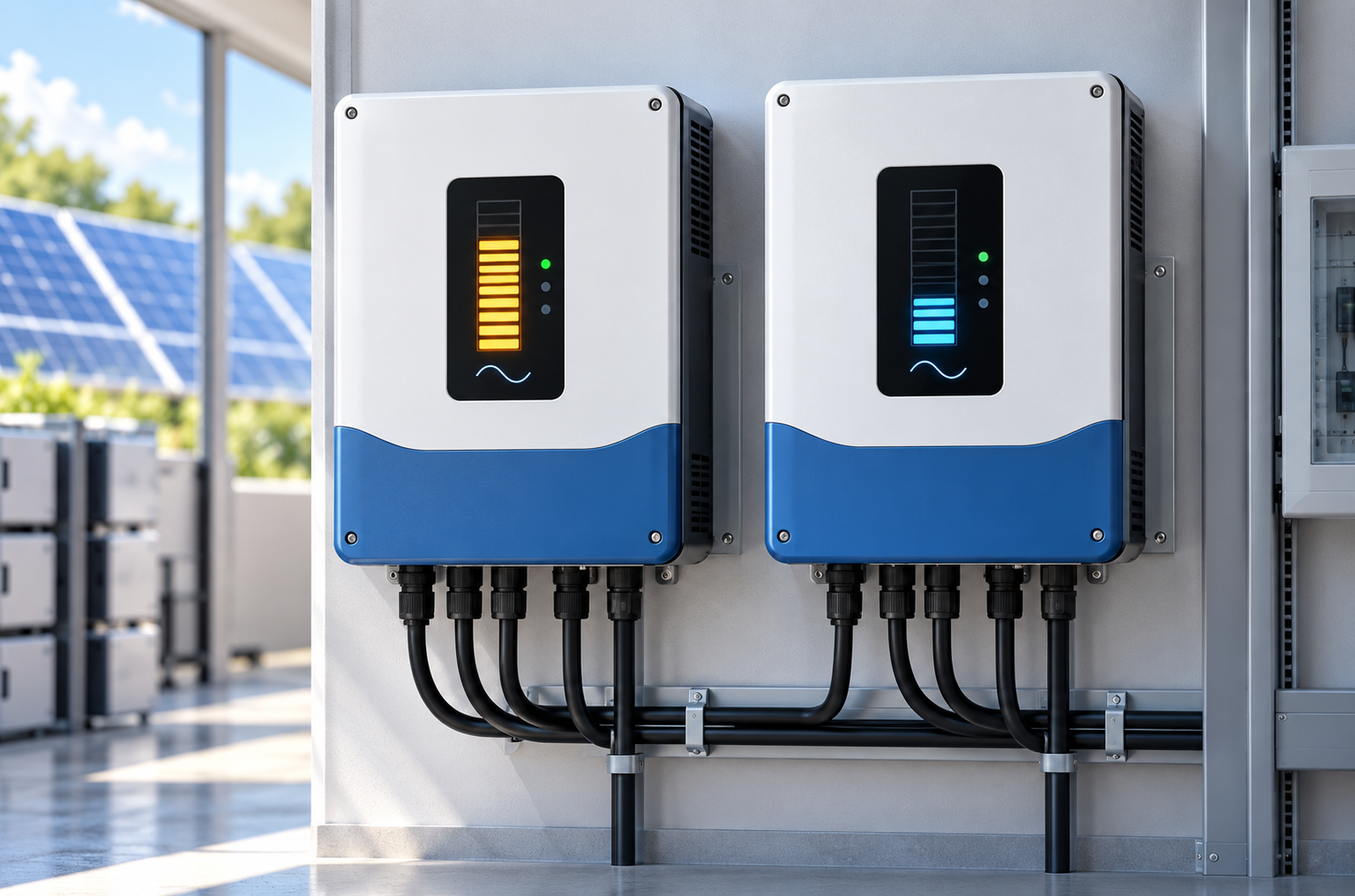
Anern inverters are designed specifically to bridge this DC (PV, battery) to AC (grid, load) gap in residential, commercial, and off-grid projects.
The role of a power inverter is to take DC power from sources like solar panels or batteries and convert it into stable, grid compatible AC power with the required voltage, frequency, and waveform.
An inverter is not a simple “converter box”—it manages:
· Switching (high-speed power electronics)
· Wave shaping (PWM + filtering)
· Voltage regulation (feedback control)
· Protection (overcurrent, short-circuit, overtemp)
· Often in solar: MPPT + battery charging + grid interaction (hybrid/ESS architectures)
Voltage-source inverter (VSI): Most common in solar and battery systems; uses a stiff DC bus and modulates output voltage via PWM.
Current-source inverter (CSI): Less common in PV; used where current control is critical.
Off-grid/stand-alone inverters: Create their own AC island for remote homes or telecom sites.
Grid-tied inverters: Match the grid’s voltage and frequency precisely to feed power back to the utility.
Learn more about solar system applications on Anern’s official Solar Power System page: https://www.anern.com/solar-power-system/
At Anern, most solar applications require DC (PV/battery) to be converted into stable AC for loads or distribution—this is why inverter selection (waveform + efficiency + protections) is a primary system-performance lever. (See Anern inverter categories here.)
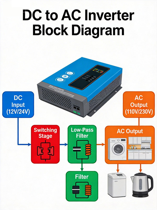
The mechanisms of DC to AC conversion in inverters describe the sequential processes of high speed switching, waveform synthesis, filtering, and control that turn a DC input into a usable AC output.
Step 1: DC input and MPPT power harvesting
The inverter first feeds PV input through an integrated MPPT (Maximum Power Point Tracking) stage that continuously adjusts the operating voltage and current of the array to its peak power point.
Compared with legacy PWM‑type solar control, MPPT can increase usable solar energy harvest by roughly 15–30%, especially in cold or variable irradiance conditions.
Step 2: High‑frequency DC‑DC conversion (MPPT stage)
Inside the MPPT stage, a high‑frequency DC‑DC converter (typically a boost or buck‑boost topology) converts excess panel voltage into additional charging current or into a stabilized DC bus for the inverter bridge.
Well‑designed MPPT stages commonly reach 95–99% efficiency, making them significantly more efficient than older PWM front ends that often operated around 70–80%.
Step 3: Sinusoidal switching bridge (SPWM or equivalent)
After MPPT conditioning, a full‑bridge (or multi‑level) inverter uses sinusoidal PWM (SPWM) or similar modulation on IGBTs/MOSFETs to synthesize a clean AC waveform from the stabilized DC bus.
Switching frequencies are typically in the tens of kilohertz range, which allows compact magnetics and precise control of output voltage and frequency.
Step 4: Filtering, synchronization, and protection
LC filters and, where required, transformers remove high‑frequency components and match the final AC voltage to the load or grid.
A digital controller coordinates MPPT, inverter switching, grid synchronization, protections, and communication, turning the device into an integrated MPPT‑inverter platform rather than a simple PWM inverter.
Step 5: Control, monitoring, and protection
Microcontrollers or DSPs regulate output voltage and frequency, synchronize with the grid, and protect against faults such as over‑current, short circuit, and over‑temperature.
Waveform quality (why “pure sine” matters)
Modern inverters commonly target THD < 5%, and higher-quality units may reach < 3%.
This matters for motors, transformers, audio, medical devices, and some switch-mode supplies.
The key components in a DC to AC conversion circuit include semiconductor switches, control electronics, passive filters, and often transformers that together synthesize, clean, and regulate AC power from DC sources.
Semiconductor switches (IGBTs, MOSFETs):
Turn on and off thousands of times per second to create the AC waveform.
MOSFETs are common in lower‑voltage/high‑frequency designs, while IGBTs dominate higher‑power inverters.
Diodes / freewheel paths:
Provide current paths during switching transitions and protect switches from voltage spikes.
DC link capacitors:
Stabilize the DC bus, reduce ripple, and provide instantaneous energy for fast load changes.
Inductors and capacitors (LC filters):
Smooth PWM pulses, reducing harmonic distortion and electromagnetic interference (EMI).
Transformers (where used):
Provide galvanic isolation and change voltage level to match grid or load requirements.
Microcontroller / DSP:
Executes control algorithms, PWM generation, MPPT logic, grid synchronization, and diagnostics.
Sensors (voltage, current, temperature):
Feed back real‑time data to the controller for safe operation and accurate regulation.
Protection elements:
Fuses, circuit breakers, surge protectors, and relays protect both the inverter and downstream equipment.
Explore Anern’s Solar Inverter portfolio for different DC to AC solutions: https://www.anern.com/solar-inverter/
Practical methods for efficient DC to AC conversion center on topology selection, advanced control techniques, and component optimization to achieve high efficiency, low distortion, and long-term reliability.
PWM‑controlled solar systems with simple inverters:
Older systems often used stand‑alone PWM charge controllers feeding a basic inverter; PWM clipped panel voltage to battery voltage, wasting the “extra” voltage and limiting efficiency to roughly 70–80% on the solar charging side.
Modern MPPT + pure sine wave inverter platforms:
Integrated MPPT solar inverters use a high‑efficiency MPPT DC‑DC stage plus a pure sine wave inverter stage, achieving MPPT efficiencies of 95–99% and overall DC‑to‑AC conversion efficiencies around 94–98%.
MPPT can boost harvested PV energy by about 15–30% compared with PWM in real‑world conditions, which is critical for medium and large systems.
High‑frequency transformer and transformerless MPPT inverters:
High‑frequency and transformerless MPPT inverters maintain compact size and still reach 96–99% peak efficiency in string and central applications.
Industry data shows that well-designed grid-tied PV inverters commonly reach 96–99% peak efficiency, minimizing system losses and improving energy yield.
MPPT (Maximum Power Point Tracking): Extracts the maximum power from PV arrays by continuously adjusting operating voltage.
Multi‑level inverter topologies: Use multiple voltage levels to reduce THD and filter size in medium and high‑power systems.
Smart and hybrid inverters: Combine on‑grid, off‑grid, and battery modes with intelligent energy management and remote monitoring.
Grid support functions: Provide reactive power, voltage ride‑through, and anti‑islanding to meet modern grid codes.
6. Comparison of DC to AC Conversion Options
The table below compares key DC to AC conversion approaches from a practical engineering perspective.
Method / Topology | Typical Use Case | Waveform Quality (THD) wevolver+1 | Typical Efficiency wevolver+2 | Cost Level battlebornbatteries+1 | Key Advantages wevolver+2 | Main Limitations wevolver+2 |
Modified square wave inverter | Low cost backup, simple tools | Higher THD (>10–20%) | ~80–90% | Low | Simple design, inexpensive | Noisy for motors, not ideal for sensitive loads |
Pure sine wave PWM inverter | Residential PV, RVs, telecom, commercial | Low THD (≈3–5%) | ≈94–98% | Medium | Grid quality power, good for electronics | More complex control and filtering |
High frequency transformer inverter | Portable power, compact ESS | Low to medium THD | >90% | Medium | Smaller and lighter hardware | More demanding thermal and EMC design |
Transformerless string inverter | Rooftop/commercial PV | Low THD (≈3% or less) | 96–99% peak | Medium to high | Very high efficiency, lower weight | Requires careful grounding and protection |
Central multi MW inverter | Utility scale PV plants | Low THD | 98–99% | High (but low per kW) | Economies of scale, advanced grid support | Single point of failure, large footprint |
1) What device converts DC to AC?
A power inverter converts DC to AC by high-speed switching and waveform shaping.
2) Can I convert 12V DC to 220V/230V or 120V AC?
Yes, use a correctly sized inverter (plus proper fusing/cabling). For higher power, 24V/48V battery systems reduce current and wiring losses.
3) What’s the difference between pure sine wave and modified sine wave?
Pure sine wave has much lower harmonic distortion and better compatibility; modified sine wave is cheaper but can reduce efficiency and increase heat/noise in some loads. (courses.ems.psu.edu)
4) How efficient is DC to AC conversion?
High-quality sine wave inverters are often rated around 90–95% efficiency depending on load and design. (courses.ems.psu.edu)
5) Why does my inverter get hot even when it “works”?
Conversion losses (switching + conduction + magnetics) become heat. Poor ventilation, undersized wiring, or operating far from the inverter’s optimal load range can worsen heating.
6) What matters more: inverter watts or surge watts?
Both. Continuous watts must cover steady loads; surge watts must cover motor starts/compressors. If you share your load list, Anern engineers can help size it for stable real-world performance.
DC-to-AC conversion is fundamentally a switching + filtering + control problem—and inverter design determines your system’s efficiency, waveform quality (THD), reliability, and load compatibility. For solar + storage and off-grid power, a pure sine wave inverter, correct sizing, good DC wiring practice, and proper thermal design are the fastest routes to stable performance.
If you’re specifying an inverter for a PV/battery project, start with your load type, surge requirements, DC bus voltage (12/24/48V), and power quality targets—then select the inverter topology accordingly. For product selection and system design support, explore Anern’s inverter and battery pages:
More related reading: