EN
 fr
 de
 es
 it
 ru
 pt
 ar
 id
 ms
 uk




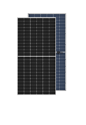
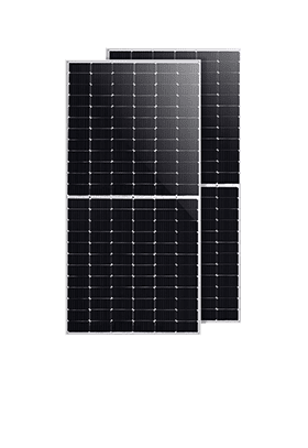
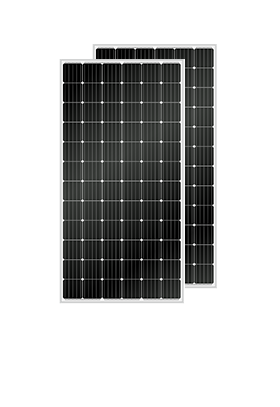
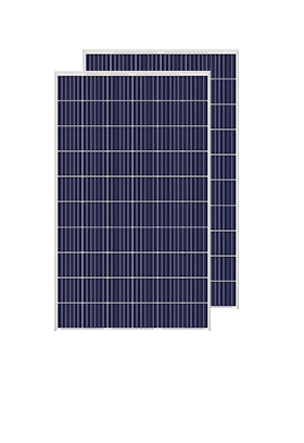



We have cooperated with more than 200 countries in solar energy projects and road lighting projects. We have exported products to many countries and participated in many important government projects around the world.




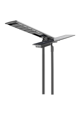


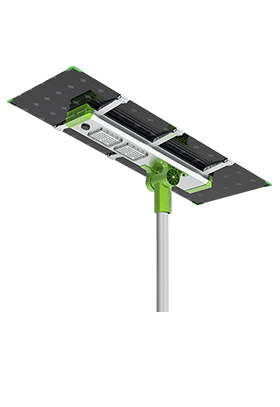
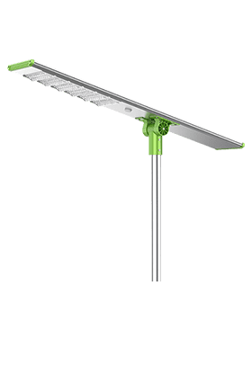
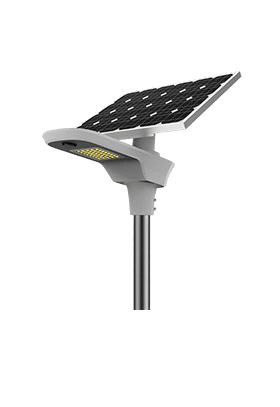


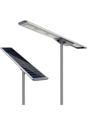
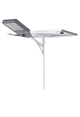
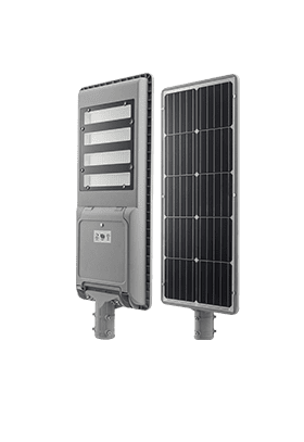
We have cooperated with more than 200 countries in solar energy projects and road lighting projects. We have exported products to many countries and participated in many important government projects around the world.

Anern has 17 years of experience in solar lighting and solar product manufacturing. Anern is headquartered in Guangzhou. With a production base of 30,000 square meters, our company has an R&D team of more than 100 people.
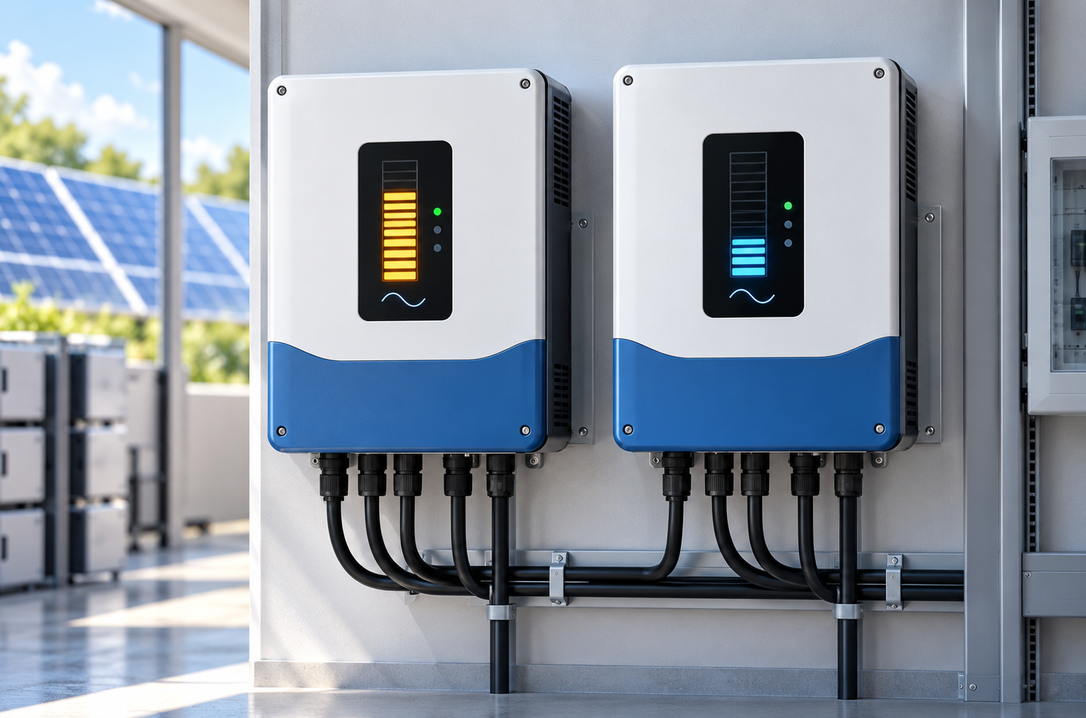
Unequal output in a solar inverter parallel connection does not automatically mean that one inverter has failed. The difference can come from operating mode, phase assignments, cable impedance, communication settings, temperature, or battery current limits. Before replacing equipment, establish whether the units are supposed to share the same load and whether the displayed readings measure the same thing.
For installers and system owners, the useful question is whether the imbalance persists under comparable conditions and reduces usable capacity. A structured comparison of AC output, DC input, alarms, and settings usually provides more useful evidence than a single screenshot showing different percentages.
Start with the system arrangement. Two units feeding a common single-phase output are different from units assigned to separate phases. A three-phase installation can show different outputs because its phase loads differ. Likewise, grid-connected units producing according to their separate PV arrays are not necessarily expected to deliver equal power. This article focuses on approved parallel inverter systems that coordinate their AC outputs.
Compare real power in watts at the same moment. Battery discharge current, PV input power, apparent power in VA, and a dashboard's “load percentage” are different measurements. Percentages may use different rating bases, and app updates may arrive at different times. Where mixed ratings are explicitly permitted, proportional sharing may be the intended behavior.
A persistent difference deserves investigation when one unit reaches its continuous rating, becomes unusually hot, or trips while another has substantial headroom. Brief differences during motor starting or operating-mode changes may be transient. There is no universal acceptable imbalance percentage: use the model's documented sharing tolerance and test conditions.
Confirm the exact model numbers, hardware revisions, firmware versions, and approved parallel accessories. Matching enclosure designs or nominal voltage does not establish compatibility. The manufacturer must explicitly support the proposed combination, unit count, phase arrangement, battery topology, and operating mode.
When selecting inverters in parallel, check the installation manual as well as the product overview. Parallel operation may require dedicated communication and current-sharing connections that are separate from monitoring or battery communication. An RJ45 socket does not necessarily use Ethernet signaling; use the specified cable pinout and connection layout.
Review the system diagram against the installation: output grouping, neutral arrangement, protective devices, and battery connections must follow the approved design. Do not join independent inverter outputs to test whether they share. Wiring inspection and electrical measurements should be performed by qualified personnel using the manufacturer's isolation procedure.
Yes, but the mechanism depends on which circuit is affected. On the DC side, additional resistance creates a larger voltage drop between the battery bus and an inverter. That unit may reach its low-voltage or current limit sooner even when both units connect to the same bank. On the AC side, unequal branch impedance can affect power sharing, depending on the control strategy. AC impedance includes both resistance and reactance.
Cable length is only part of the comparison. Conductor cross-section, material, routing, lugs, fuse holders, breakers, and termination condition all affect the complete path. Equal-length cables do not compensate for a loose or damaged connection. Use the manufacturer's specified cable layout; do not insert extra resistance as a balancing adjustment.
For an illustrative DC calculation, an extra 0.005 ohm in a branch carrying 100 A causes a 0.5 V drop and dissipates 50 W. This illustrative calculation shows how a small increase in connection resistance can cause significant heating under load.
Record voltage at the common battery bus and each inverter's DC terminals under the same operating condition. A larger drop on one branch is evidence to investigate. Isolate the circuit and verify that it is de-energized before measuring resistance or working on terminations.
Parallel controllers need a consistent view of the system. Depending on the design, master selection, unique unit addresses, phase allocation, communication termination, or current-sharing links may need specific configurations. A running inverter can still have an incorrectly configured communication path, so an illuminated display alone proves little.
Compare output-voltage and frequency settings, operating priorities, charging limits, and relevant firmware. A hybrid inverter parallel connection may behave differently in battery mode, utility bypass, and PV-assisted operation. Confirm whether the imbalance occurs in every mode or only during one transition. Do not copy menu values between unlike models simply because the labels appear similar.
Separate generation from output sharing. Unequal solar panel arrays can produce different PV input readings without proving unequal AC load sharing. Shading and array orientation belong in the operating record, but changing PV wiring is not a general cure for a parallel-output problem.
A battery management system can reduce permitted discharge current because of temperature, state of charge, cell voltage, or a protection event. An inverter that obeys this restriction may appear underloaded even though its power stage is healthy. Check the allowed current reported by the BMS alongside actual current and alarms.
In a shared-bank arrangement, compare the battery-bus voltage with the voltage seen by each inverter. If the whole bus falls, investigate the available battery power and bank condition. If the bus remains stable but one inverter sees a larger drop, its branch deserves closer inspection. Systems using separate banks require a different comparison and must be explicitly supported by the inverter design.
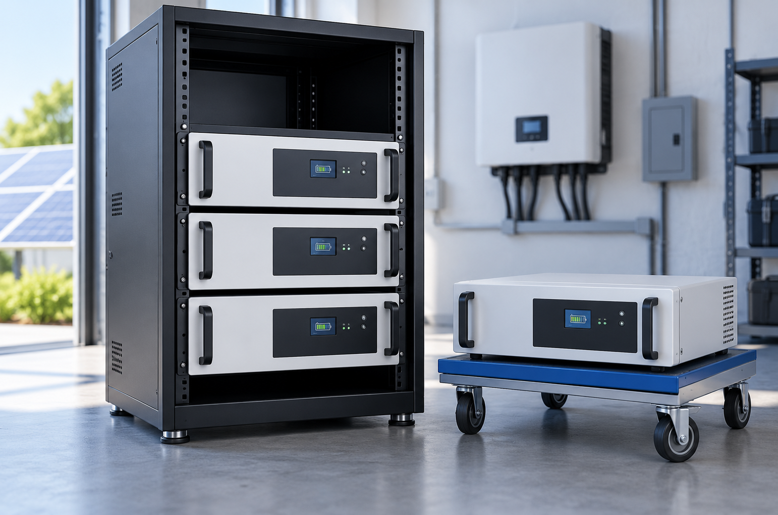
The selected lithium battery must supply the required continuous current through correctly rated power connections. Where BMS communication is required, its protocol and cable must also be compatible with the inverter. More stored kilowatt-hours do not guarantee sufficient instantaneous power. Also inspect cooling conditions: obstructed airflow or higher local temperature can cause one inverter to derate before the other.
Capture synchronized data during a stable load period, then during a controlled load change within the system's rating. Keep the original fault and alarm history before resetting anything. A factory reset can remove information and alter required settings without addressing the cause.
Record | What the comparison helps establish |
Model, firmware, unit address, and phase | Whether the installed configuration matches the approved system |
AC watts, VA, voltage, and current per unit | Whether the difference is real-power sharing or a measurement issue |
Battery-bus and inverter-terminal voltage | Whether a DC branch has excessive voltage drop |
BMS allowed current, state of charge, and alarms | Whether the battery is restricting operation |
PV input and operating mode | Whether generation or source priority explains the readings |
Temperature and fan status | Whether thermal derating is reducing one unit's output |
For example, 3.0 kW and 1.0 kW from two equal-rated units on the same phase warrant a different investigation from 3.0 kW and 1.0 kW on separately loaded phases. The numbers alone cannot distinguish these cases. A single-line diagram and a time-aligned record make the difference interpretable.
If the discrepancy remains after configuration and external conditions are verified, provide the logs to technical support. Manufacturer-directed testing can then separate sensing, control, and power-stage faults. Avoid swapping live cables or disconnecting communication leads while the system is operating.
No. Sharing depends on the approved configuration, unit ratings, control mode, and measurement accuracy. Compare steady-state values against the manufacturer's tolerance rather than expecting identical display numbers at every instant.
Only if limited battery capability is the verified cause. Extra capacity will not repair an incompatible firmware combination, an AC wiring error, a poor terminal connection, or a failed sensor.
The master designation does not by itself establish a higher power allocation. It often identifies a control or communication role. Check the model documentation before treating a persistent difference as normal.
Only when the complete arrangement is explicitly engineered and approved for that purpose. Sharing a utility grid does not establish that their backup outputs can be connected together or operate safely as one islanded system.
Diagnose a solar inverter parallel connection by confirming the intended sharing behavior first. Compare synchronized AC measurements, verify approved hardware and settings, and distinguish cable voltage drop, BMS restrictions, and thermal limits from inverter faults. This sequence helps identify the actual constraint before components are replaced or system capacity is expanded.
· U.S. Department of Energy — UNIFI Consortium: Grid-Forming Inverter Research. Background on inverter operating roles and coordinated controls.
· Sandia National Laboratories — Electrical Energy Storage Data Submission Guidelines, Version 3. A framework for selecting useful battery and power-system operating records.
· Sandia National Laboratories — Commissioning Overview: A Safety Focus. System commissioning, BMS monitoring, and verification of control behavior.