EN
 fr
 de
 es
 it
 ru
 pt
 ar
 id
 ms
 uk




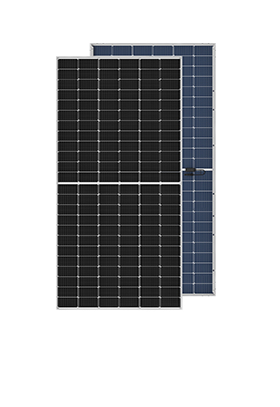
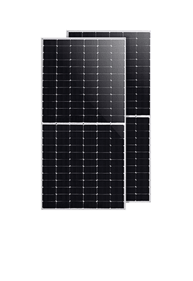
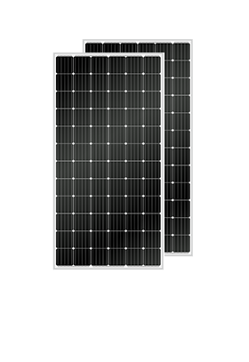
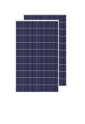



We have cooperated with more than 200 countries in solar energy projects and road lighting projects. We have exported products to many countries and participated in many important government projects around the world.




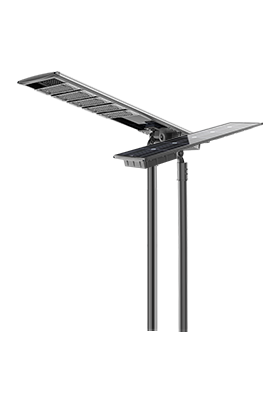


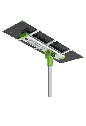
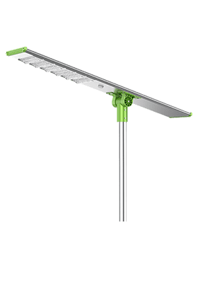
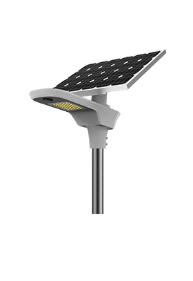


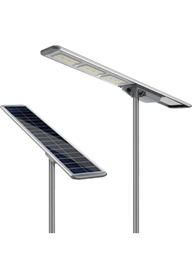
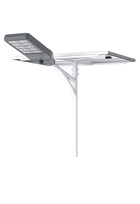
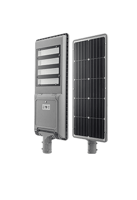
We have cooperated with more than 200 countries in solar energy projects and road lighting projects. We have exported products to many countries and participated in many important government projects around the world.

Anern has 17 years of experience in solar lighting and solar product manufacturing. Anern is headquartered in Guangzhou. With a production base of 30,000 square meters, our company has an R&D team of more than 100 people.
A lithium battery rack can sometimes be expanded with new modules, but matching the label voltage and physical dimensions is not enough. The battery manufacturer must permit the combination of models, ages, firmware, and parallel topology. The inverter, protective devices, busbars, and rack must also support the enlarged system.
Expansion is most useful when the existing bank is healthy but cannot provide the required operating hours. If short runtime comes from an undercharged bank, a disconnected module, or deteriorating cells, adding batteries may leave the original problem unresolved. Start by measuring the shortage, then check whether expansion is the appropriate remedy.
Look at several representative operating cycles. Does the bank reach its intended charge level before evening? Does it consistently reach the configured reserve before the required backup period ends? Have new overnight loads been added? These observations distinguish an energy-capacity shortage from insufficient charging or an output-power limit.
Estimate the additional energy at a clearly defined boundary. An extra 500 W load running for four hours needs 2 kWh at the AC load. Battery-side demand will be higher because of inverter losses and auxiliary consumption. Required nameplate storage will be higher again if only part of the battery's capacity is available within the permitted operating window.
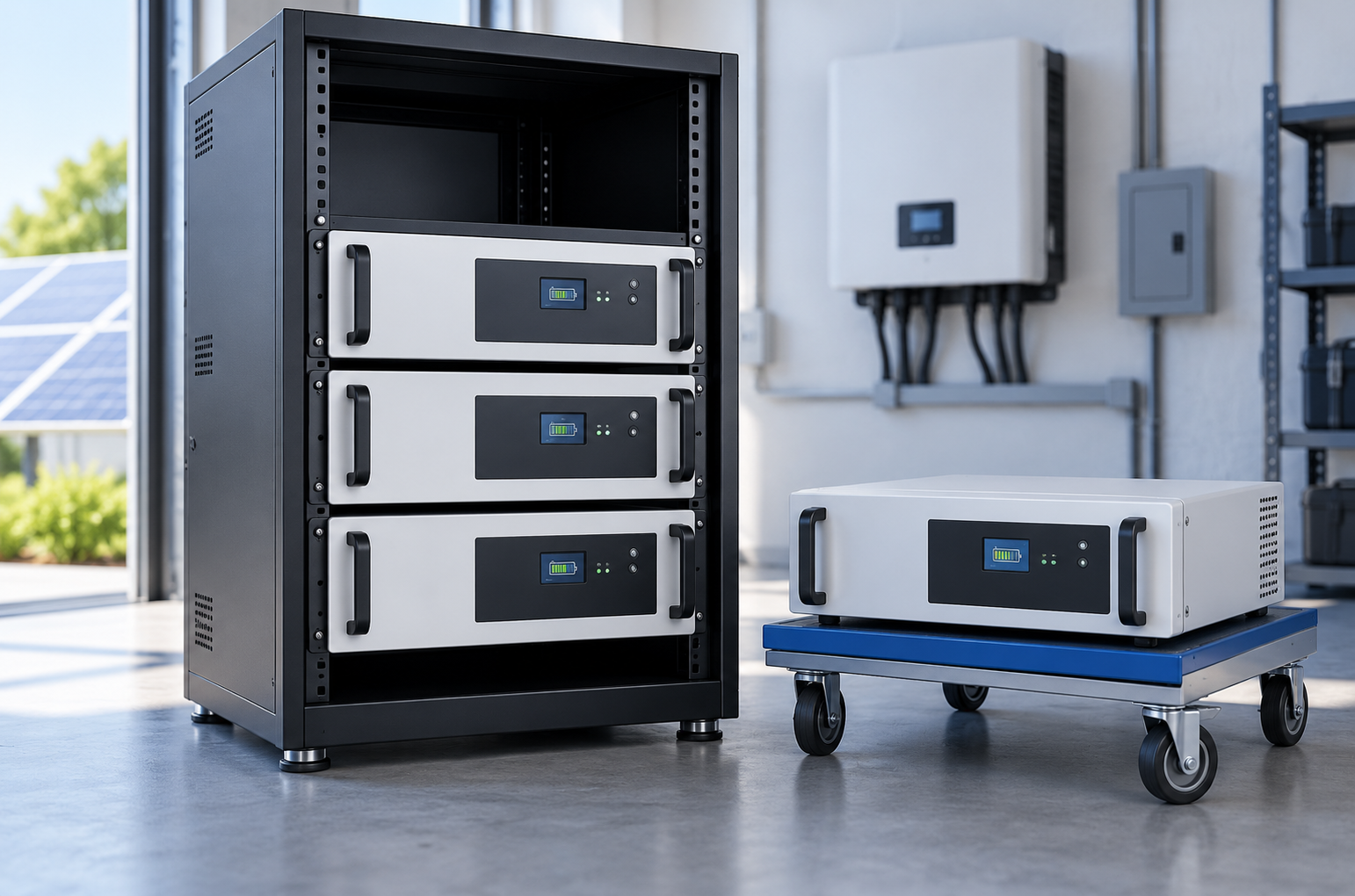
For a rack mounted lithium battery system, compare usable energy with the actual load profile before deciding how many modules to add. A larger bank also takes more energy to recharge. If the solar array already struggles to replenish daily use, storage expansion alone will not create additional solar generation.
They can in some approved systems, but there is no universal age limit or universal permission to mix them. Check the permitted battery family, cell chemistry, series-cell configuration, operating-voltage range, capacity combinations, and maximum module count. A “48 V” category can include products with different nominal voltages and charging requirements.
Older modules may have less usable capacity and different internal resistance. In parallel operation, current does not necessarily divide equally, particularly when connection resistance, temperature, or state of charge differs. One module can reach a protective limit earlier, leaving the remaining modules to support the load. A common rack does not make these differences disappear.
Review module-level history: cycle count, measured capacity where available, cell-voltage spread, temperature events, and repeated protection alarms. A damaged or persistently abnormal module should be investigated before expansion. Do not use a new module to mask a weak module's behavior.
Before connection, follow the manufacturer's specified voltage and state-of-charge matching procedure. Lithium iron phosphate has a relatively flat voltage curve over much of its operating range, so similar terminal voltages alone do not prove equal state of charge. Connecting modules at unequal voltages can produce a high equalization current. Installation requires the prescribed isolation, connection, and startup sequence; do not assume hot-swapping is permitted.
Where the system uses closed-loop BMS communication, the configured battery controller must recognize the enlarged bank and report the supported operating limits to the inverter. Confirm the supported protocol, cable pinout, firmware combinations, master arrangement, addressing method, and communication termination. Having CAN or RS485 ports on both devices does not prove that their protocols match.
For a 48v rack mount lithium battery, use the exact model and hardware revision when checking compatibility. An updated module may look identical while using a revised controller. Firmware should be changed only according to the supplier's supported procedure, with the existing settings and versions recorded first.
For systems with a master battery controller, verify after expansion that it reports the correct number of available modules and the supported aggregate current limit. A powered module that is absent from communications may not contribute as expected. Keep battery-to-battery communication separate from the inverter link in the documentation so that each part can be checked independently.
More storage usually means more available energy, measured in kilowatt-hours. It does not automatically increase the system's AC power rating, measured in kilowatts. Output remains constrained by the inverter, the BMS, battery branch ratings, common conductors, protective devices, and thermal conditions.
As a hypothetical example, two approved 5 kWh modules provide 10 kWh nominal storage. If their approved combined continuous discharge limit is 200 A at an assumed 51.2 V, the corresponding DC power is about 10.24 kW before conversion losses. A 5 kW inverter still cannot supply 10 kW continuously. Actual module combinations and discharge limits must follow the specifications for the selected battery system.
The reverse also matters: a larger inverter cannot draw its rated power if the battery permits less current. Review both charge and discharge limits, including their temperature dependence and duration. When selecting a lithium battery, compare nominal and usable energy, continuous power, and short-duration output capability alongside ampere-hour capacity.
An empty rack position is only the starting point. Check module depth, rail support, total weight, anchoring, access to isolators, and the required ventilation and service clearances. Do not block terminals, cooling paths, or labels to fit an additional unit.
The common busbar and outgoing cable may carry more current after expansion even if each module retains its original branch cable. Protective coordination and available fault current must also be reassessed. More parallel sources can increase fault energy, so simply adding branch fuses does not confirm that the existing main device remains suitable.
Expansion check | Evidence needed before proceeding |
Module combination | Written compatibility information for model, revision, and age or condition limits |
Mechanical support | Rack dimensions, load rating, anchoring, and clearance requirements |
DC current paths | Approved branch and common-bus design, cable ratings, and terminations |
Protection | Correct device ratings, interrupting capability, and isolation arrangement |
Controls | Supported firmware, addressing, protocol, and maximum recognized module count |
Charging supply | Enough charging capacity and available energy for the intended operating cycle |
Use the specified connection topology to keep branch impedances appropriately balanced. Avoid extending an improvised daisy chain simply because another connector is accessible. The electrical design should show how every module reaches the common positive and negative connection points.
Commission the expanded bank as a complete system. Confirm polarity, protective devices, communication recognition, settings, and startup status before applying the planned load. Verify module availability and the inverter's received charge and discharge limits rather than relying only on the bank's combined state-of-charge display.
Observe module current, cell-voltage spread, temperature, and alarms through controlled charging and discharging within approved limits. The goal is to identify unexplained differences or early protective cutoffs. Perfectly equal current at every instant is not a universal acceptance criterion; the expected behavior depends on the supported combination and control design.
Record the new configuration, serial numbers, firmware, connection diagram, and baseline performance. Check whether the added capacity actually extends the required load period and whether normal charging can restore the bank afterward. If the result falls short, distinguish unavailable modules, charging limitations, reserve settings, and conversion losses before assuming the new batteries are defective.
Only if the manufacturer explicitly permits those exact models in the same bank. A shared voltage label does not establish current-sharing behavior, communication compatibility, or the correct aggregate limits.
Follow the manufacturer's compatibility matrix. Some systems require matching versions; others support specified combinations. “Latest firmware” is not automatically the correct version for an older controller.
Not necessarily. At the same charging power, a larger amount of stored energy takes longer to replenish. Additional modules may permit more charging current, but the inverter, charging source, wiring, and controls must also allow it.
Replacement may be more appropriate when testing shows poor capacity, recurring faults, or an unsupported mixed-module combination. Expansion is best assessed after the existing bank's health and charging performance are understood.
Expand a lithium battery rack only after confirming an actual energy shortage and an approved module combination. Check battery health, BMS integration, current paths, protection, and charging capacity together. A successful expansion adds usable operating time while keeping the complete system within its documented electrical and mechanical limits.
· U.S. Department of Energy — Solar Integration: Solar Energy and Storage Basics. Stored energy, output power, conversion losses, and variable solar supply.
· Sandia National Laboratories — Commissioning Overview: A Safety Focus. System commissioning, BMS monitoring, and verification of control behavior.
· Sandia National Laboratories — Electrical Energy Storage Data Submission Guidelines, Version 3. A framework for selecting useful battery and power-system operating records.